•
|
• |
|
|
Lesson Objectives In this tutorial you will learn the basic steps for launching to orbit. You should complete the tutorials for Preflight Preparations, Taxing, Ground Run Up, and takeoff procedures prior to beginning this tutorial. At the end of this tutorial you should exhibit knowledge related to launching into orbit procedures. The following subjects will be presented.
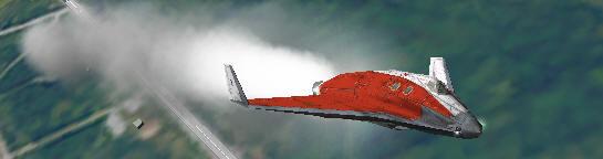
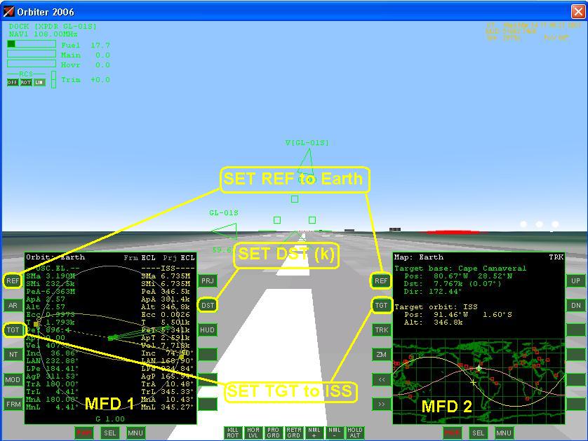
Section 1: Preflight Launching into orbit requires four crucial elements: heading, pitch attitude, delta v, and engine burn time. These factors will determine what inclination, altitude, and all other orbital elements that affect your flight. The accuracy of your orbit at launch largely depends on your ability to hold these calculated values. The calculations to determine your heading, pitch altitude, delta v, and engine burn time are tedious. These calculations are simplified through the use of appropriate performance charts referrer to Mission Planning Lesson. As part of your preflight you should complete a Mission Flight Log. Your work load as a pilot astronaut is greatly reduced by thoroughly filling out a flight log and using your mission flight plan. Using a flight log will help you gauge your performance and flight path by comparing it to the predicted values in the performance charts. It will also help you use your fuel efficiently. Before launching into orbit complete the Instrument Cockpit Check List. This will enable you to determine what parameters you will need to fly to obtain your desired orbit. Suppose we want to rendezvous with the International Space Station Figure1.1.
Orbital Mode
Map Mode
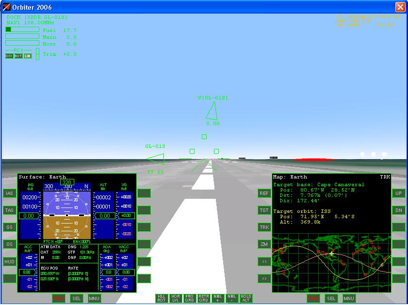
Complete the following Checklist Items: Section 2: Take Off Complete the normal take off procedures as you would for a surface flight, however be sure to turn on the Reaction Controls System (RCS) it should be set to the rotation mode. Do as much of the instrument set up as you can before launch this will save you time and stress later on in the flight. Heading From your Mission Flight Plan you should have already determine what heading you will fly. In the Map mode on the MFD you can get a rough idea of the heading that is required to match the ground track of ISS's orbit. It is to the south east or a heading of 162.76 degrees. After taking off turn to this heading. Once you are established on this heading pitch the nose up and increase engine thrust to full throttle. Hold a pitch attitude between 70 and 80 degrees as you climb into orbit. When you are ready to take off start the flight timer and record your take off time. Apply full power and proceed with a normal take off, if you are on a planet with no atmosphere you have to follow the procedures for a vertical take off. Once airborne turn to your initial heading that you calculated previously in the performance charts and simultaneously set your pitch attitude to climb into orbit. Pitch Attitude Deciding what pitch attitude to use depends on several factors such as atmospheric density, target interception, space craft performance, and fuel consumption. Typically we want to have a high pitch attitude between 70 and 80 degrees to clear the atmosphere of the planet. Atmospheric drag increase the amount of fuel used to reach orbit. After we have gained sufficient altitude where atmospheric drag is negligible we then use a much lower pitch attitude, between, 20 and 30 degrees, to increase our horizontal velocity relative to the surface of the planet. Doing so will allow us to reach the necessary speed for a circular orbit, see Figure 2.1 and 2.2. This technique is quite useful because it will reduce the amount of fuel consumed to reach orbit.
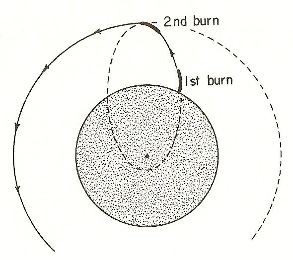
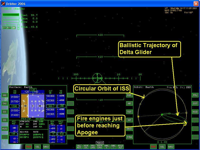
Section 3: Initial Engine Burns Launching into orbit requires two separate engine burns, or if you get really good one burn. The first engine burn will place the space craft on a ballistic trajectory. A second engine burn is required to reach the necessary velocity for a circular orbit, with out it the space craft would simple fall back to surface. On the first engine burn we will turn the engine on and hold a pitch attitude until our projected Apogee is the same as that of the International Space Station. Once those two values match shut down the engine and let the space craft coast up to Apogee. When the current altitude and Apogee of the space orbit match fire the engine a second time, and lower the pitch attitude, this will increase the orbital velocity of the space craft and raise the Perigee of the orbit. The goal is to reduce the eccentricity of our space crafts orbit to that of a circular orbit. Initial Burn The first engine burn will set the apogee of your orbit and put the space craft on a ballistic trajectory. Hold your pitch attitude and heading as you begin to climb. The precision that you fly you heading and pitch will determine what kind of orbit that you will have. Make minor adjustment to your pitch and heading too correct for any errors in you orbital parameters such and inclinations and longitude of the ascending node. Monitor your Apogee and shut down your engines when it reads the desired value. Note that this value is not the same as your current altitude. The ApA displayed in the Orbital Mode shows you your current apogee this should not be confused with you current altitude. The time that has elapsed should correspond to you calculated value from the performance charts.
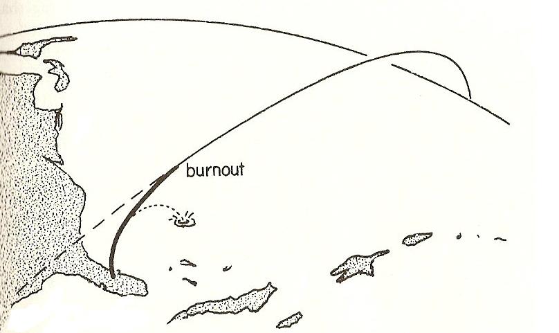
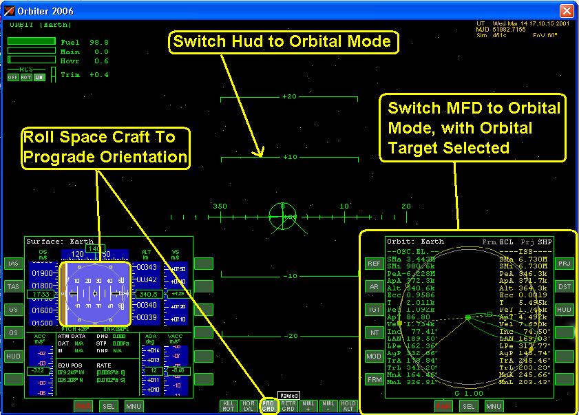
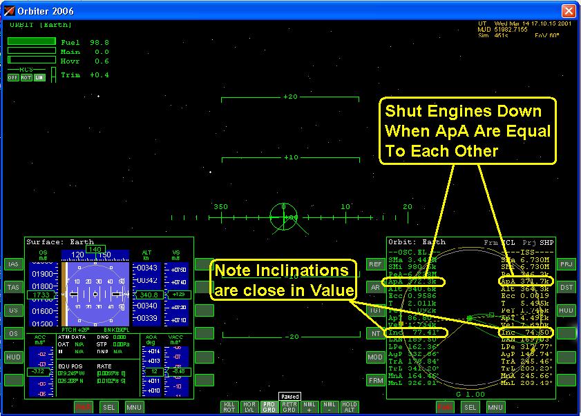
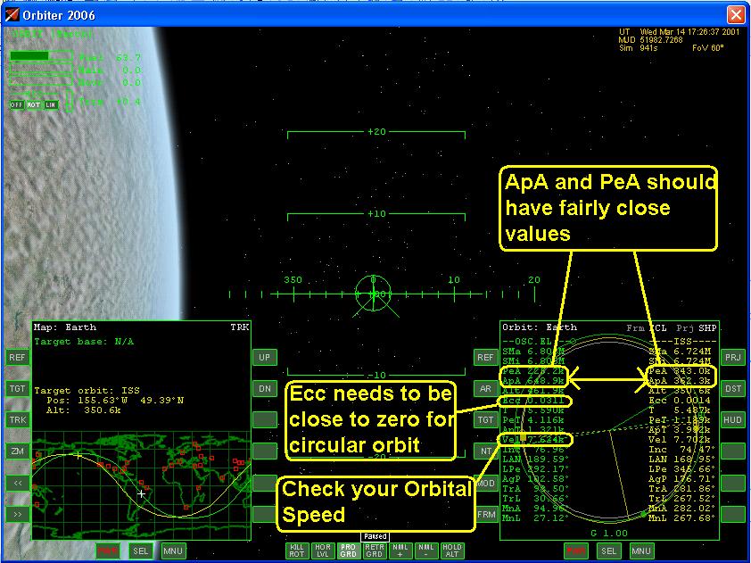
Section 4: Fire Engine To Circular Orbital Speed A second engine burn will be required to reach the required orbital velocity, with out the second burn your space craft will follow a ballistic trajectory and crash into the planet's surface Figure 4.1, and Figure 2.3. Activate the auto pilot by selecting the Prograde command. You no longer need hold you pitch attitude. Just before you reach Apogee fire your engines and increase your orbital speed to match the necessary speed for a circular orbit. Once you've reach your orbital speed shut the engines down and note that you burn time should be close to what you calculated on your flight plan. Check your Orbital Elements Values Figure 4.2. The values for Eccentricity (Ecc) should be close to zero, and the Perigee (PeA) point of the orbit should increase, ideally this value should match the PeA of the target orbit. At the very least PeA should be high enough to clear the atmosphere of the planet. If this is not accomplished the Delta Glider will experience atmospheric drag and will fail to achieve orbit. The distance for Apogee (ApA) may have increase slightly as well. Your orbit may not exactly match what your intended orbit, but is should be relatively close. The next step will be to correct our Apogee and Perigee altitude.
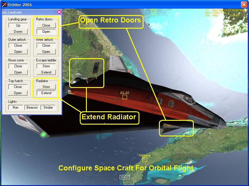
Complete the following Checklist Items: Section 5: Configure Space Craft for Orbital Flight Once the space craft has reach a stable circular orbit configure it for orbital flight, by follow the check list (Figure 5.1 and 5.2). This would include deploying any space craft systems needed for orbital operations, such as: radiator, solar cell panels, RCS doors, etc.
Complete the following Checklist Items: Section 6: Completion of the Launching Into Orbit Now that you are in orbit proceed to the next phase in your mission, this could be docking with another spacecraft or space station, orbital or planetary transfer, or deploying a satellite. Section 7: Summary Check List - Launching Into Orbit Listed below is a summary of the check list used in this lesson. A check list provides using abbreviated steps to help remind you of the action items that you need to take. They are listed here as a quick reference guide and are sited through out this lesson.
|
|
|
Send mail to
customerservice@fly-zero-g.com with
questions or comments about this web site.
|