duydr

• Home • Up • Feedback • Contents • Search • MAA Store • Store By Amazon •


Home
Up
Docking CL
Post Docking CL


Docking Procedures

Lesson Objectives

In this tutorial you will learn the basic steps for Docking Procedures. The following subjects will be presented.

  1. Concept

  2. Instrument Set Up

  3. 8 Ball Maneuver

  4. Docking Procedures

  5. Completion of the Maneuver

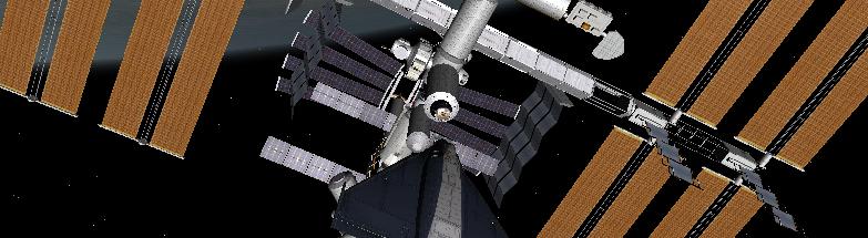
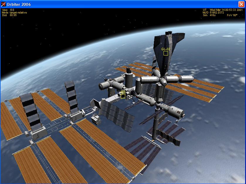
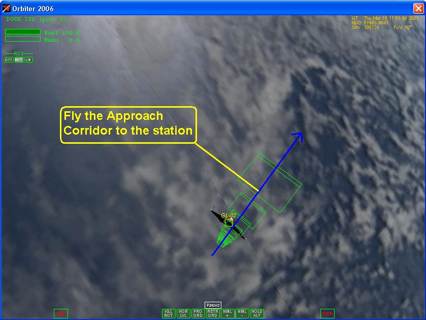
Section 1: Concept

After rendezvousing in orbit with the target vessel the next task is to accomplish a successful approach so that both vessels can dock with each other. Docking require skill and care in its execution. Your space craft should be with in 10 km of your target, complete the docking checklist at this time.  Bring the space craft to1 km of the station by using short burst from the main engine. Monitor your closure rate speed (cvel) very carefully if it gets to fast slow down using the retro engines. If it is too high you will fly right by the station. A closure rate of about 30 to 80 m/s is fairly good value depending on how far away you are from the target. Slow down as you approach the 1 km mark of the station and perform the "8 Ball Maneuver". This will maneuver will bring you to the initial fix of the approach that starts at the beginning of the approach corridor. Follow the approach corridor to make a successful dock with the target.

Figure 1 Glider Dock with ISS

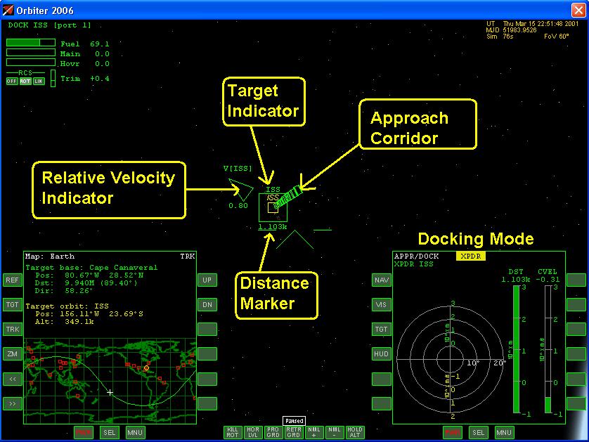
Section 2: Instrument Set Upt1

The Docking MFD assists during final approach to dock with another vessel or orbital station. It provides indicators for translational and rotational alignment with the approach path, as well as distance and closing speed readouts.

Figure 2a Docking Mode MFD1

Figure 2b Docking Mode MFD2


Figure 2c Visual Mode

This instrument relies on docking approach data received by your spacecraft. Approach data can be acquired in three different modes:

  • IDS (Instrument Docking System) mode - data are acquired from a radio signal sent by the docking target. The IDS  signal is obtained by tuning a NAV receiver to the appropriate frequency and slaving the Docking MFD to that receiver. The typical range for IDS is ~100km. Select the appropriate a NAV receiver and frequency for the station docking port. The selected frequency is displayed in the upper right corner of the MFD.

  • Visual mode - Docking parameters are acquired from onboard visual systems (typically video cameras mounted in the docking port. The visual system aids in docking to targets which don’t provide IDS. The typical range for visual mode is ~100m.
  • Direct target selection -  If you want to avoid the need to tune into a navigation transmitter  signal, you can open target dialog box and enter target name (and optional docking port index) directly. (This shortcut method may be dropped in a future version). Apart from their different operational range, the three modes provide are identical in terms of the produced MFD display.
  • IDS source - identifies the source of the currently received IDS signal.
  • TOFS - tangential offset from approach path. This value is given in units of the approach cone radius at the current target distance. TOFS < 1 indicates a position inside the approach cone.
  • TVEL - Tangential velocity (velocity relative to target, projected into plane normal to approach path) [m/s]
  • DST - Dock-to-dock distance [m]. The bar shows the distance on a logarithmic scale in the range 0.1–103 m.
  • CVEL - Closing speed [m/s]. The bar shows the closing speed on a logarithmic scale in the range 0.1–103 m/s. Yellow indicates positive closing speed. The circular instrument shows the ship’s alignment with respect to the approach path towards the allocated dock.
  • Approach path indicator - The green cross indicates the position of the approach path relative to the ship. When centered, the ship is aligned on the approach path. The radial scale is logarithmic in the range 0.1–103 m. Tangential alignment should be performed with attitude thrusters in linear mode.
  • Tangential velocity indicator  -  The yellow arrow indicates the relative tangential velocity of your vessel with respect to the target. The radial scale is logarithmic in the range 0.01–102 m/s. The numerical value is the tangential velocity [m/s]. To align your ship with the approach path, engage linear attitude thrusters so that the arrow points towards the approach path indicator.
  • Alignment indicator - The white/red cross indicates the alignment of the ship’s forward direction with the approach path direction. When centered, the ship’s forward direction is parallel to the approach path. The cross turns red if misalignment is > 2.5°. The radial scale is linear in the range 0–20°. Rotational alignment should be performed with attitude thrusters in rotational mode.
  • Longitudinal rotation indicator - This arrow indicates the ship’s longitudinal alignment with the docking port. To align, the indicator must be moved into 12 o’clock position by rotating the ship around its longitudinal axis, by engaging bank attitude thrusters in rotational mode. When alignment is achieved, the indicator turns white (misalignment < 2.5°). Note that this indicator is only displayed when directional alignment is within 5°.
  • Approach cone - The concentric red or green circle indicates the size of the approach cone at the current dock distance. The ship should approach the dock so that the approach path indicator is always inside the approach cone (indicated by a green circle). The approach cone becomes smaller as the ship approaches the dock. Closing speed should be reduced as the ship approaches the dock (using retro thrusters). The final speed should be < 0.1 m/s.

Complete the checklist items for the instrument for set up:

bullet Docking Checklist

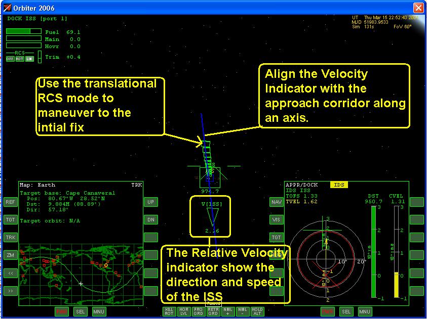
Section 3: 8 Ball Maneuver

The 8-Ball Maneuver is used to fly your vessel to the initial fix of the approach corridor. Image a 1 km sphere that surrounds the station, see 8-Ball Maneuver Lesson for further details. The idea is too always keep the nose of the Delta Glider pointing towards the station as you move across the surface of an imaginary sphere. Maintain your distance of 1 km as you travel along circular path to the initial fix of the approach corridor. The 8-Ball Maneuver will require that you constantly switch back and forth between the rotational and translational RCS modes to maintain your distance and orientation. With practice this will become easier for you. The rotational mode of the RCS is used to keep the nose of the space craft pointing towards the station. The translational mode of the RCS is used to move across the surface of the 8-Ball. Use the translational RCS thrusters to maintain a constant distance Figure3a and 3b. 

Figure 3a The 8-Ball

Figure 3b HUD display

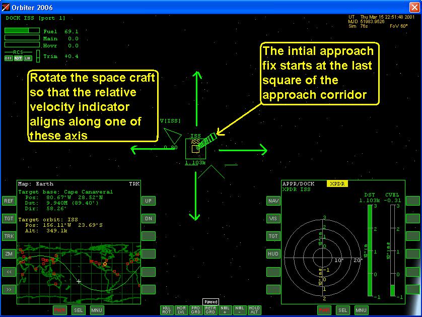
Moving a long the 8-Ball is largely a matter of technique. An easy method is to rotate the space craft so that the Relative Velocity indicator is along one of the axis depicted in Figure 3c. Then use the rotational and translational modes to maneuver to the initial fix.

Figure 3c Move along the 8-Ball

Figure3d Align with the docking port

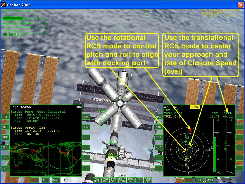
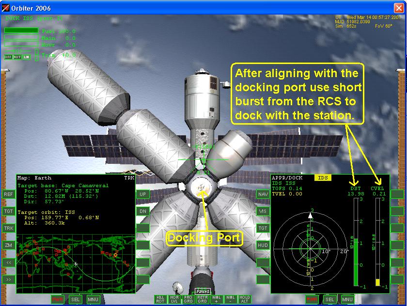
The 8-Ball Maneuver is complete once you reach the initial fix (Figure 3d), from there you can proceed to the docking port.

Section 4: Docking Procedures

  1. Instruments set up complete.

  2. Proceed from the Initial Fix to the docking port using small bursts of thrust from the Reaction Control Jets (RCS). Use the rotational RCS mode to control your pitch alignment and your roll alignment. The translational RCS mode is used to center your approach and adjust your closure speed, Figure 4a.

  3. Once you are aligned with the docking port use short burst of thrust and slowly approach the station , Figure 4b.

  4. When you distance reach zero you will have hard dock and will be attached to the docking port of the ISS, Figure 4c.

  5. To dock successfully, you must approach the dock to within 0.3 m. Additional restrictions may be implemented in the future (speed, alignment, etc.) No collision checks are currently performed. If you fail to dock and keep closing in, you may fly your ship through the target vessel.

Figure 4a Use RCS mode to align with docking port

Figure 4b Approach the ISS

Figure 4c Docked at the ISS


Figure 4d The Approach Corridor

Use the checklist to complete the procedures:

bullet Docking Checklist

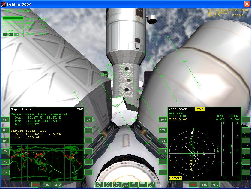
Section 5: Completion of the Maneuver

The maneuver is complete once you have successfully docked with the ISS. Follow the crew transfer checklist, then move crew members to and from the station Figures 5a, 5b, and 5c. Follow the check list and secure the space craft.


Figure 5a Open Outer and Inner Airlocks

Figure 5b Transfer Crew Members


Figure 5c Crew Members on the Delta Glider

Use the checklist to transfer crew members:

bullet

Post-Docking Checklist

Section 6: Summary Check List - Docking and Post Docking

Listed below is a summary of the check list used in this lesson. A check list provides using abbreviated steps to help remind you of the action items that you need to take. They are listed here as a quick reference guide and are sited through out this lesson.

bullet Docking Checklist
bullet

Post-Docking Checklist

Citation:

Pictures:

1-Orbiter Space Flight Simulator, 2006 Edition User Manual, Martin Schweiger, pg 58-60

2-Orbiter Space Flight Simulator, 2006 Edition User Manual, Martin Schweiger, pg 58-60

Text:

t1-Orbiter Space Flight Simulator, 2006 Edition User Manual, Martin Schweiger, sec13.5


Home ] Up ] Docking CL ] Post Docking CL ]

Send mail to customerservice@fly-zero-g.com with questions or comments about this web site.
Copyright © 2005 Millennium Aviation & Aerospace
Last modified: 01/26/11