•
|
• |
|
|
Lesson Objectives In this tutorial you will learn the basic steps for Base Synchronization that illustrates the procedure for adjusting the orbit of space craft to align with a landing sight for reentry. The following subjects will be presented.
Suggested Reading Topics:
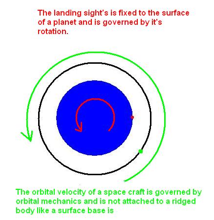
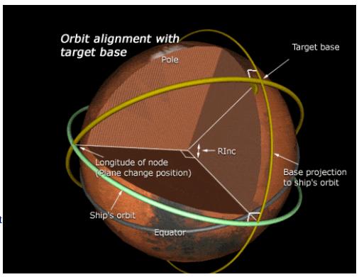
Module Installations: Sections 1: Concept When a spacecraft is returning to land at a spaceport or other landing location, it must align and sync it's orbit with the landing location. During orbital rendezvous each vessel has its own orbit elements, and one simple matches his current orbital element to that of the target vessel by changing his inclination apogee and so forth. This is not necessarily the case when landing at a space port, because of verity of factors such as atmosphere. and rotation of the planet and must be taken into account. The landing base does not have a traditional orbit, because it is attached to a ridge body that is has its own rotation speed and may be located on a planet that has an atmosphere, Figure1. The orbital elements of the base can be displayed on some MFDs. The techniques we use to compensate for the rotation of the planet and atmosphere are different from orbital rendezvous and require the use of BaseSync and AeroBrake MFDs
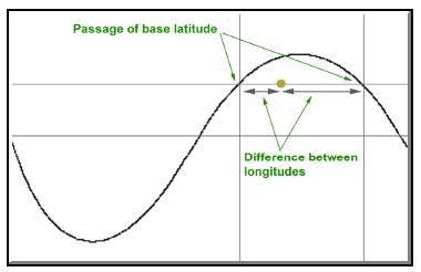
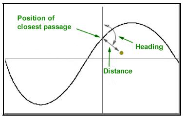
Section 2: BaseSync MFD The Base Synchronization can be used to align the orbit plane, and deorbit a space craft, with a landing location on the surface of a planet. Synchronization can be accomplished by selecting the target ground base or entering the latitude and longitude of the landing site. The green line marks the space current position and the yellow line and text indicates the closet intercept to the landing site, Figures 2.1 and 2.2.
Section 2.1: Encounter Modes The encounter mode gives the pilot astronaut four options on how to sync the orbit of the space craft to a particular landing site. The four modes are:
Section 2.2: Equator and Direct Modes The BaseSync MFD also has two inclination adjustment modes that are used to adjust the inclination of the orbit.
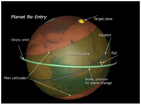
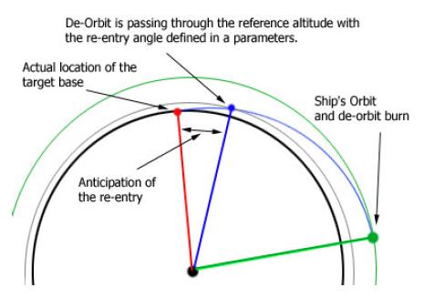
Section 2.3: De-Orbit Program The De-orbit mode is used on the orbital plane is adjust to be in sync with target base or landing site. The program requires three parameter to calculate reentry path: reentry angle (ReA), reference altitude (RAI), and reentry anticipation angle (Ant). Each parameter can be selected using the buttons on the MFD, Figure 2.7.
The reentry angle is the angle between the local horizontal and the velocity vector of a reentering space craft, Figure 2.8
The reference altitude is the altitude that the space craft will mostly likely encounter the atmosphere of the planet. For planets that have no atmosphere the reference altitude is zero. The reentry anticipation angle is the angle from the point where the space craft reaches the reference altitude and the target base, or landing site, Figure 2.9.
Section 3: Instrument Setup The BaseSync MFD is the primary navigation aid used during reentry to align and synchronize your orbit with a target landing site or base. Use the following procedures to set up the BaseSync. BaseSync MFD
Use the following checklist to ensure that the flight instruments are set up correctly. Citation: Pictures: 1,2,3,4,6 Base Synchronization Manual, Jarmo Nikkanen 5 Returning from Space, FAA
|
|
|
Send mail to
customerservice@fly-zero-g.com with
questions or comments about this web site.
|