|
Lesson Objectives
In this tutorial you will learn the basic steps
and concepts for
Aerodynamic Braking and the effects that the atmosphere has on a space craft. The following subjects will be
presented.
-
Concepts
-
AeroBrake MFD
-
Instrument Setup
Suggested Reading Topics:
-
4.1.7 Returning from Space (PDF)
-
ORBITER Space Flight
Simulator Manual - 2006 Edition Sections: 16,
19.3
-
Delta-glider
Operations Manual
-
Aerodynamic Braking Manual
Module Installations:
-
AerobrakeMFD
Section 1: Concepts
During space flight the two
governing forces that act on a spacecraft are the thrust produced by our engines, and gravitational
influences, or centripetal force. Do to the vacuum of space orbits and flight trajectories are fairly
straight forward to calculate. As a space craft reenters the atmosphere it will
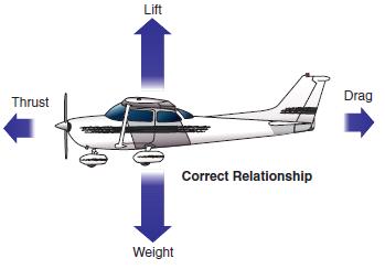
encounter two other forces lift and drag. All four of these forces lift,
thrust, gravitational force (weight), and drag, fall under the subject of
aerodynamics.
-
Thrust is the force that is provided by the propulsion system
of the space craft.
-
Gravity is the primary force that acts on a space craft
in the vacuum of space, and is exclusively governed by planetary bodies.
Its strength is determine by the distance between the space craft and the planet
it is orbiting.
-
Weight is also a gravitational force, it is treated as a
constant value when the space craft is relatively slow and close to the surface
of a planet.
-
Lift is produce by the geometry of the vehicle as it
moves through and interacts with gas, or fluid.
-
Drag is the byproduct of lift and is primarily affected by
how stream line the object is, or how easily it can pass through a gas
with the least amount of disturbance.
|
 |
 |
|
Figure 1.1 Forces Non-atmospheric Flight |
Figure 1.2 Forces atmospheric Flight |
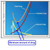
During atmospheric reentry these four force can be used to
determine where you will land and govern the flight path of reentry vehicle,
Figure 1.3.
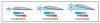
It is important to understand the aerodynamics involved in the types of design
for reentry vehicles and how it will
produces lift. The design of a reentry vehicle with wings can travel
father then ones that don't. This will affect the type of reentry techniques
that you will use. The engineers during the Apollo, and Gemini, programs used a space capsule
that produced very little lift. This design meant that the distance in could
travel relative to the ground was shorter when compared to the Space Shuttle's
airplane like design. The wings allow the Space Shuttle to travel a greater
distance but at the cost of having a greater launch weight. There are advantages
and disadvantages to each design. So it is important to
understand the geometrical design of the space craft and the amount of lift that
it will produce.
|
 |
 |
|
Figure 1.3 Flight Path |
Figure 1.4 Angle of Atack |
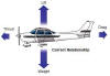
Power off reentry primarily use gliding
techniques to control the flight path of the vehicle. This is done by changing
the pitch attitude of the space craft. The angle formed between the relative
flight path and the wing, or lifting surface, is called the Angle of Attack (AoA),
Figure 1.4.
Adjusting the AoA, by pitching the nose of the spacecraft up or down will
change the aerodynamic forces acting on the space craft. To increase the drag
force pitch the nose up, lowering the nose will decrease it. Increasing the drag
will increase the amount of deceleration that we experience and shorten the
horizontal distance traveled. For winged vessels there is a limit to how much we
can increase AoA to produce drag. The wings will stop producing lift at the
critical Angle of Attack because the air will no longer flow smoothly over it
and will stall.
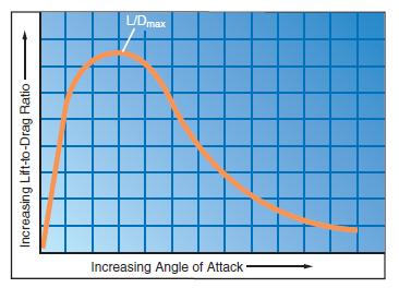
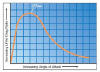
To travel the greatest distance with out the use of power
requires that we have the least amount of drag. This is determined by the Lift
to Drag ratio (L/D), it will have a maximum only at a
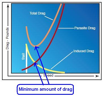
specific AoA, Figure 1.5. Drag will have a minimum at a given airspeed and is
controlled by the AoA, Figure 1.6. This means that
there is an interplay between or angle of attack, airspeed, and drag. These
factors are determined by altitude, temperature, and air density,
|
 |
 |
|
Figure 1.5 Lift to Drag Ratio |
Figure 1.6 Drag verse Airspeed |
Section 2: Aero Brake MFD
The aerodynamic calculation for vehicle flying through the atmosphere are
compounded by variable changes in air density, temperature, and aircraft
geometry. The Aero Brake MFD is a sophisticated module that calculates the flight
path of space craft as it travels through a planets atmosphere and can be use to
plan a descent to a landing site, or space port.
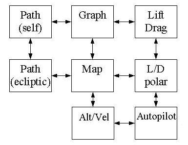
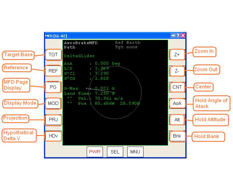
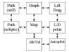
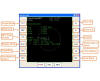
There are several pages that can be navigated to in the Aero Brake MFD.
Figure 2.1 illustrates the software structure of the MFD. Use the PG
button to navigate to different pages, and the PRJ button to display different
data on each page, Figure 2.2
|
 |
 |
|
Figure 2.1 Aero brake software structure |
Figure2.2 Aero Brake MFD Display |
Section 2.1 :Aero Brake MFD Pages
Path Page:
Displays the orbit around a planet, and has the ability to
zoom in closer to landing sites. A yellow bar appears to show your relative
position, with a cross on top for finer alignment. Changing the projection
will help you evaluate errors in position, range, and course.
Graph Page:
Shows the current trajectory. The first
projections display performance data: velocity, altitude, and distance travel.
The second projection displays space craft integrity: heat flux, and
deceleration . If the deceleration is above 10 g's a red line appear
giving an indication of strong sollecitation, or oscillations. The distance
may indicate a different value then what is displayed on other MFDs, this is
because the true distance may change due to planet rotation, and time spent in
the air.
Map Projection:
Displays the ground track across the
surface a planet. The displays is similar to the Map MFD except that the path
displayed is the real path of the space craft, and not apiece of the orbital
path. This is because the Aerobrake MFD takes into account the
aerodynamic effects of the atmosphere, and rotation of the planet. A small
target window will open when a landing sight is picked. It can be used for
fine adjustment to the landing sight. The integral path uses current data from
lift and drag to compute distance values, and my vary as the spacecraft
decelerates through the atmosphere.
Alt/Vel Graph:
Plots altitude and velocity. There are four types of
velocity plotted for any given altitude: circular velocity, escape velocity,
minimum lift and equilibrium velocity, maximum lift and equilibrium velocity.
The velocity values displayed are only valid when your vertical speed is zero.
Circular Velocity:
When ships velocity is below this value you will descend
towards the planet. If it is above this value you will climb away from the
planet.
Escape Velocity:
When ships velocity is below this value, the trajectory
will be on a captured orbit around the planet. If it is above this value you
will be on an escape trajectory from the planet.
Minimum Lift And Equilibrium Velocity :
Displays the velocity value when aerodynamic forces are in
equilibrium using the greatest Angle of Attack for steady flight. This display
is useful for a feathered reentry, where you decelerate using the less dense
upper atmosphere to free fall to a different altitude.
Maximum Lift And Equilibrium Velocity:
Lift and Drag Page:
Stores data during flight for each angle of attack. The
graph displays two gray lines for the the lift and drag force acting on the
space craft. The green line is the Lift to Drag (L/D) ratio. The maximum L/D
ratio is the angle of attack with the longest glide path. The maximum Lift has
a corresponding stronger Drag, so there is greater deceleration.
Auto Pilot Response page:
Displays the delta and rate of
change with respect to a desired value. If the autopilot is properly
calibrated, a spiral line will appear towards the center, other wise a
wandering line will form. A PID algorithm parameters file will need to be written in
the ships description file to properly calibrate the auto pilot.
-
P parameter is for Proportional, the autopilot applies a
force that is proportional to the sum o differences from the reference value.
-
I parameter is for Integral: the autopilot applies a force
that is proportional to the sum of difference from the reference value.
-
D parameter is for Derivative: the autopilot applies a
force that is proportional to the rate of change of currently measured value.
Section 2.2 Buttons:
-
Target - used to select a space port
-
Reference - used to selects the planet you want to use
-
Page - use to scroll through the different MFD pages
-
Mode - there are two modes that can be selected flight
information, and spacecraft performance
-
Projection - displays different trajectories, or views,
depending on which page your on
-
Zoom (+/-) - changes the dimensions and magnification of maps
that are displayed
-
Center - used to center the display on planet, ship position,
and target base
-
AoA Autopilot - turns AoA autopilot on or off to maintain a
specific Angle of Atack (AoA) using RCS thruster
-
Alt Autopilot - turns the Alt autopilot on or off to
maintain altitude by using the trim and elevator
-
Bank Autopilot - turns the Bank autopilot on or off to
maintain a specific angle of bank.
Sections 2.3 Display Information:
-
Reference Planet - the planet you are currently orbiting
-
Target - base to land at
-
Autopilot - displays the current autopilot mode, and
reference value
-
Angle of Attack - show current angle of attack
-
Lift/Drag ratio - displays best L/D for maximum glide
distance
-
S*Cl - Lift Coefficient shows the current lifting force
-
S*Cd - Drag Coefficient shows the current drag force
-
Velocity Difference - gives indication of how much velocity
is being lost
-
Max. Deceleration - indicates the number g's experienced by
the pilot
-
Perigee Altitude - displays current altitude at perigee above
the ground
-
Time to Perigee - time left to reach perigee or ground
contact
-
Velocity at perigee - ship velocity at perigee
-
Perigee position - given in longitude an latitude or ground
contact point
-
Apogee Altitude - gives altitude of apogee relative to the
surface
-
Eccentricity - actual orbit eccentricity, used in aerocapture
-
Target Position - given in longitude and latitude
-
Target distance - the relative distance from ship to landing
point
-
Equilibrium Velocity - the velocity at with aerodynamic
forces are equal. When flown at that velocity the ship will stay at the current
altitude, when less then that velocity the spacecraftt will descend
-
Maximum Velocity - the maximum velocity with the lowest
angle of attack that can be flown to maintain the current altitude.
-
Minimum Velocity - the minimum velocity
with the greatest angle of attack that can be flown to maintain the
current altitude
-
Maximum L/D - the AoA with maximum efficiency that will give
you the greatest distance that you can glide
-
Minimum L/D - the AoA with minimum efficiency that will give
you the least amount of distance that you can glide
-
Maximum Lift - the AoA with the maximum lifting forces
-
Minimum Lift - the AoA with minimum lifting forces
-
Maximum Drag - the AoA with the maximum drag force
-
Minimum Drag - the AoA with minimum drag force
Section 4: Instrument Setup
The AeroBrake MFD is the primary used to help determine your
flight a path as you pass through a planets atmosphere. It can be used
plan your reentry orbit with a target landing site or base. Use the following
procedures to set up
and AeroBrake MFDs. Further details will be given in the Deorbit and Reentry
Lesson.
AeroBrake MFD
-
Select TGT and enter the landing base, Figure3.2 and 3.3.
-
Select the PG to map mode.
-
Select the HDv and enter the hypothetical delta v if
necessary.
Use the following checklist to ensure that the flight instruments are set up
correctly.
|