•
|
• |
|
|
Lesson Objectives In this tutorial you will learn the basic steps for Deorbiting Procedures. The following subjects will be presented. The deorbiting procedures outline here are very aggressive and use a lot of fuel, they may not work for some types of space craft. Modify them as desired to suit your purposes.
Suggested Reading Topics:
Section 1: Concept Deorbiting is required when you want to land on the surface of planet, moon, or asteroid. The location on the surface of a planetary body could be a space port landing pad, runway, or in rough rugged terrain. Deorbiting utilizes a combination of orbital maneuvers to reentry a space craft, such as: Orbital Plane Alignment, and Transfer Orbits. Reentry is affected by several crucial elements: heading, pitch attitude, delta v, ballistic range, atmospheric conditions, and engine burn time. These factors will determine what kind reentry you have. The accuracy to land at a specific point depends largely on your ability to hold these parameters. The calculations to determine your heading, pitch altitude, delta v, and engine burn time are tedious. These calculations are simplified through the use of appropriate performance charts referrer to Mission Planning Lesson. Your work load as a pilot astronaut is greatly reduced by thoroughly filling out a flight log for deorbiting. Using a flight log will help you gauge your performance and flight path by comparing into the predicted values in the performance charts. It will also help you use your fuel efficiently. As part of your pre-deorbiting procedures you should complete a Mission Flight Log. The basic step to deorbiting and reentry are:
Section 2: Using A Navigational Beacon A Navigation Beacon can be used as target when moved to a landing site or runway. It can provide useful information for the navigation systems when selected as a target in the different MFD modes. Prior to starting this lesson you should have completed the lesson "Creating A Navigation Beacon". For illustration purposes we moved the Beacon to the end of runway 31 at Cape Canaveral, Florida, our desired landing location. The Beacon can easily be moved to any location on planets surface that you choose to navigate too.
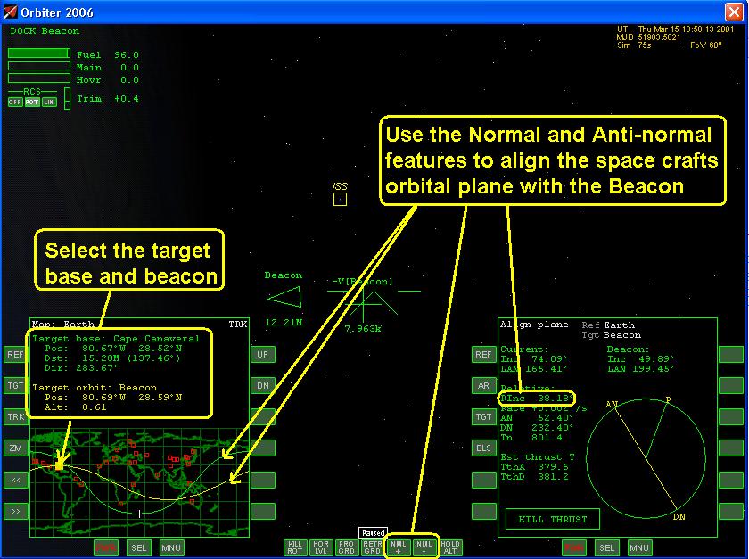
Section 3: Instrument Setup We will use the Beacon and the information we get from it to supplement our primary navigation aid which is the BaseSync, and AeroBrake MFD modes. The following procedures can be used in an emergency if our BaseSync MFD fails. You can skip this section if you do not want to use the Beacon as back up to your main navigation aid. Now that the Beacon has been created, we can program the various MFD modes to get the necessary navigation information that we need. The following describes what information can be gleamed from the different MFD modes during reentry. The features in each of these instruments were not intended to be used during reentry, however if used properly they can provide useful information that will aid the pilot. The Align Plane Mode will give us information that can be used to align our space craft's orbit to the correct inclination of the landing sight. The HUD in the Docking System Mode can give used as a visual reference indicating the direction of the landing sight and its relative movement to the space craft. It is a useful aid to the pilot during the reentry and landing procedure indicating the direction and relative movement of the target. The Transfer Mode can be used to gauge how far from the target that the engines should be fired for reentry. It will indicate at what point during the orbit that the engines need to be fired. The Map Mode gives a visual reference that shows the impact point of the space craft on the planet surface. The Orbital Mode gives the current Orbital Elements of the Beacon as it travels along the planets surface. Follow the steps listed below to program the MFD. Starting with the Align Plane Mode and then program the subsequent navigation systems, Figure 3a, begin by:
Use the following checklist to ensure that the flight instruments are set up correctly. Deorbiting and Reentry Instrument Set Up :
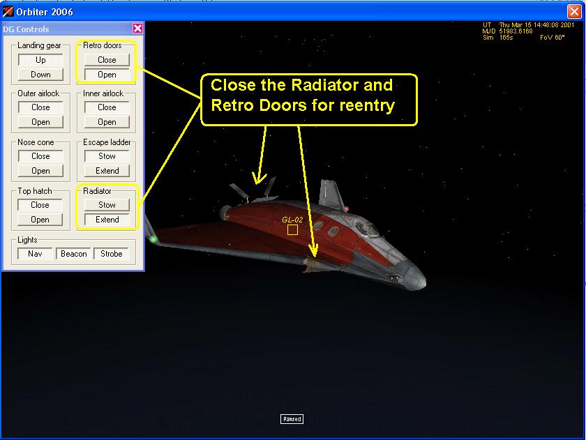
Section 4: Space Craft Configuration Before we can reentry the atmosphere of a planet we need to configure the space craft so that will not burn up due to heating. Follow the Deorbit Procedures Check List to ensure that all of the airlocks, landing gear, and radiator are properly configured and stowed, Figure 4.
Deorbit Procedures:
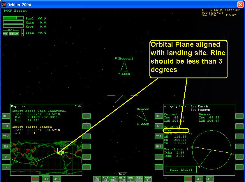
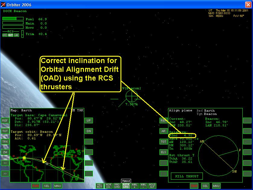
Section 5: Deorbiting Procedures Once we have properly configure the flight instruments we can now proceed with deorbiting the space craft. Start by aligning the space crafts orbital plane with the orbital plane of the landing sight, Figure 5a and 5b. The procedures are basically the same as those outlined in the Align Orbital Plane Lesson. One major difference is that the landing site is fixed to the surface of the planet and moves as the planet rotates. As the landing point moves it will create an Orbital Alignment Drift (OAD), Figure 5c, that you will have to constantly correct for. Ideally you will want to complete the deorbit procedures in one or two orbits any more than that and the OAD will be too great and you'll have to start all over again with the alignment procedure. The Relative Inclination (RInc) should be less than 3 degrees. You can make fine adjustments using the RCS thrusters. The RCS thruster are two weak to have any effect if RInc is greater than 3 degrees, and you will have to use the hover thrusters to perform the Pop Can maneuver to correct angle (See Pop Can Maneuver Lesson for more details).
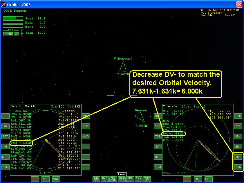
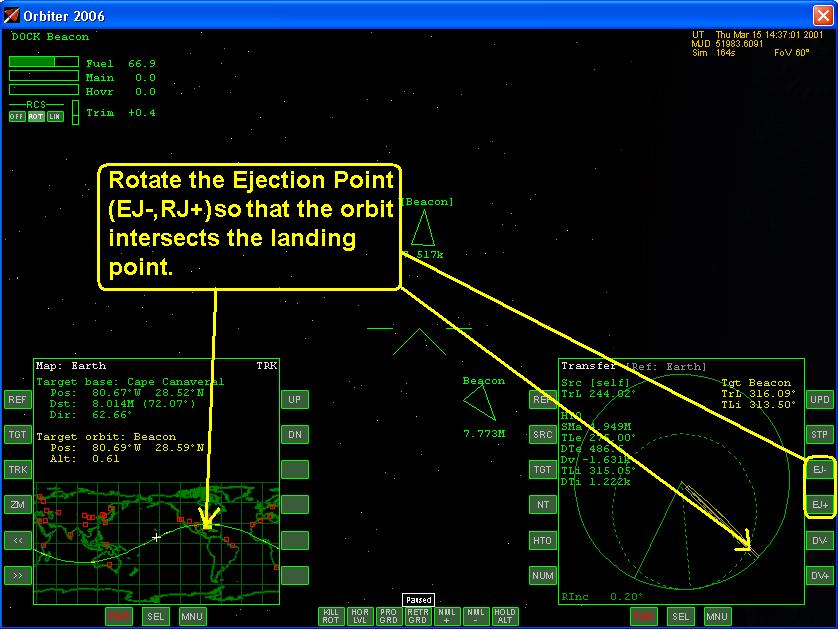
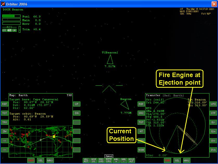
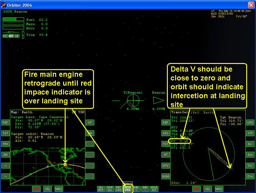
After aligning the orbital planes, roll the spacecraft retrograde in preparation for deorbit burn. The space craft needs to decrease our orbital speed to change the shape of our orbit to intersect the landing site. Two things are required during reentry when to fire the main engine, and how much delta v is needed to change the orbit. Both of these pieces of information are provide by the MFD Transfer Mode. Select the MFD Transfer Mode and select the Beacon as the target. From our performance charts we determine the desired orbital velocity of 6000 m/s (6.000 k) that would be required for reentry. We can then determine what delta v is required to get this value by subtracting our current orbital speed is 7.631 k and a delta v of -1.631 k to get 6.000k (7.631 k -1.631 k=6.000 k). This is an aggressive deorbit that uses a lot of fuel, shallower orbits with smaller reentry angles are better and use much less fuel. Now that the delta v has been determine enter this in on the Transfer Mode MFD, Figure 5d. Adjust the Ejection Point so that it aligns with the landing site, Figure 5e. The Transfer Mode will display you current position, and the Ejection Point where you would fire the engine for reentry, Figure 5f and 5g. Use the display read out to determine delta v, and time to Ejection Point.
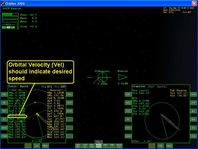
When you reach the Ejection Point fire the main engine retrograde stop when the Orbital Velocity reaches the desired value in the MFD Orbital Mode Figure 5h. Cross check that the impact point is over the landing site, this is indicated by the red square in the Map Mode, Figure 5i.
Section 6: Pop Can Maneuver Once you are satisfied with the engine burn to deorbit roll the spacecraft prograde and perform the Pop Can Maneuver. The Pop Can Maneuver is used to correct the alignment plane because of Orbital Alignment Drift. This can be accomplished by keeping the nose pointed prograde and rolling the space craft normal or anti-normal such that the hovering thruster can be use to correct the Relative Inclination (RInc), see Figures 6a, 6b, and 6c. Some may not like this type of technique, or is inappropriate for the space craft that their flying. It is useful because the pilot can maintain his or hers orientation to the landing site.
You can also use the Pop Can maneuver to adjust the impact point (red square) at the landing site by firing the engines radial inward (-r) or radial outward (+r). Section 7: Reentry Procedures Now that we are aligned with our desired landing site we can prepare for reentry. There are many factors that will affect your reentry performance. We must take into consideration whether the reentry will require lifting or non-lifting techniques. For a lifting reentry we will have to take into consideration the atmospheric conditions of the planet that we are landing on. Lifting reentry requires a transition from the vacuum of space to smooth stable aerodynamic airflow over the wings. Heating consideration must also be taken into account, too step of reentry angle and our space craft will burn up: too shallow and our space craft will skip like rock off of the atmosphere back into space. Non-lifting reentry do not have these conditions that we would have to worry about because of the lack of atmosphere around a planet. In either case it is important that we configure the space craft correctly for the type of reentry that we will be performing. The following checklist can be used to configure the space craft correctly. Reentry Procedures:
With spacecraft now in its proper configuration we will then use the Auto Level feature to level the space craft to the local horizon of the planet, Figure 7a. The trim should be set to zero and the Auto Level on to allow for a smooth transition to atmospheric flight. This gives a 0 degree pitch attitude which may not be appropriate for all space craft. The shuttle enters at a much shallower reentry angle, with an angle of attack (AoA) of about 40 degrees. Once we are level, or at reentry attitude (Angle of Attack), we now must make a GO, or NO-GO, decision. If we have to abort reentry we fire the main engines and climb back into orbit. This would not be possible with the shuttle since it main engine do not have the capability of an orbital-go-around. We would have to abort reentry if our orbital speed is to fast, reentry angle to steep, or relative inclination to great, this would be cause for a NO-GO decision. At the reentry interface with the atmosphere the nose of the space craft should be pointing in the direction of flight (Prograde), if not the aerodynamic force will cause it to tumble and burn up.
In this example the spacecraft is reentering the Earth's atmosphere to land at Cape Canaveral. At about 80 kilometers is when the space craft will start to encounter the atmosphere and aerodynamic forces would take over. If the space crafts pitch attitude is to high it will climb back up if it is too steep, or nose down, it will burn up, Figure 7b. For a lifting reentry, turn off the RCS thruster once the space craft is stable and utilize the aircraft flight controls. When the space craft is at an appropriate altitude, 3000 ft to 5000 ft above the ground, engage the Hold Altitude (Hold Alt) function and deploy the airbrakes if necessary to slow down, Figure 7d and 7e. The hover engines may come on to hold altitude. When the airspeed reaches about 200 m/s to 600 m/s, retract the airbrake and descend to 10 kilometers, or an appropriate altitude, to set up for the approach to land on the runway, landing pad, or landing site. For shallower reentry angles the techniques are complete different.
Section 8: Completion of the Maneuver The Deorbit and Reentry procedure is complete when you have successfully passed through the atmosphere of the planetary body and have set up for the approach to land. The elements for reentry are to align the orbital planes, set a range to fire the main engine and to enter the atmosphere at the appropriate reentry angle.
Citation: Pictures: 1-Orbiter Space Flight Simulator, 2006 Edition User Manual, Martin Schweiger, pg 67-68 2-Orbiter Space Flight Simulator, 2006 Edition User Manual, Martin Schweiger, pg 47 |
|
|
Send mail to
customerservice@fly-zero-g.com with
questions or comments about this web site.
|