•
|
• |
|
|
Lesson Objectives In this tutorial you will learn the basic steps for changing the Apogee and Perigee of and orbit. The following topics will be discussed.
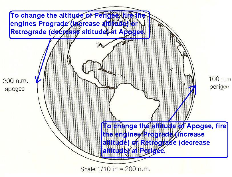
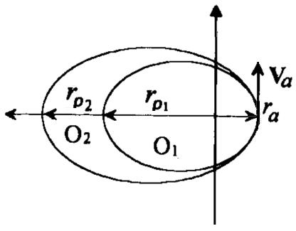
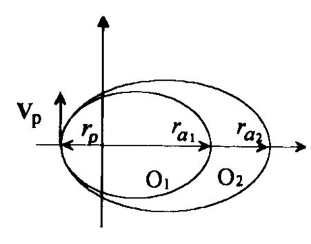
Section 1: Concept of Change Apogee or Perigee Altitudes, and Circularizing an Orbit During a mission in may be necessary to make corrections to an orbit by making changes to the apogee or perigee altitude. Apogee is the highest altitude that can be obtained during an orbit, where as perigee is the lowest point in an orbit. Both apogee and perigee effect the eccentricity of an orbit, or how oblate the orbit is compared to a perfectly circular orbit. To change the altitude of perigee we will fire the engines at apogee. Firing the engines prograde will increase the perigee altitude, and firing the engines retrograde will decrease perigee altitude, Figure 1a and 1b. If we want to change the apogee altitude we will need to fire the engines at perigee. Once again firing the engines prograde will increase apogee altitude, and firing them retrograde will decrease apogee altitude. For large corrections use the main engine and the Reaction Control Jets (RCS) for small corrections, Figure 1a and 1b. To circularize an orbit we must adjust either the apogee or perigee, as appropriate, until the eccentricity of the orbit is approximately zero, pr when the apogee and perigee altitudes are the same. This may take some practice but play with it and see what happens.
Figure 1b show the various orientations that a space craft can be in during its orbit. The orientation is referenced to the direction of travel of the space craft as it orbits a planetary body. The orientation of the space craft is determined by which way the nose is pointing for each maneuver. If you are instructed to turn the space craft prograde it means to point the nose of the spacecraft in the direction of travel in the orbit. Retrograde means to point the nose in the opposite direction of travel or 180 degrees from prograde. (See the lesson Orientation in Space)
The table below list the possible ways to change the apogee or perigee altitudes, use this table to determine what orientation the space craft needs to be in order to get the desired results. Table 1: Changing Apogee or Perigee.
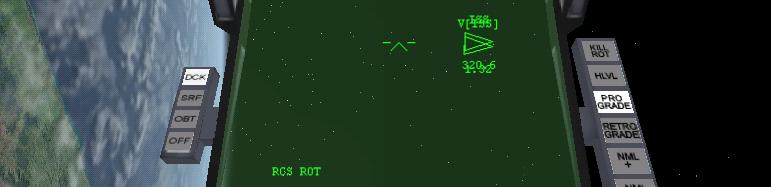
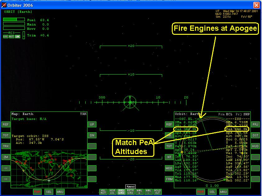
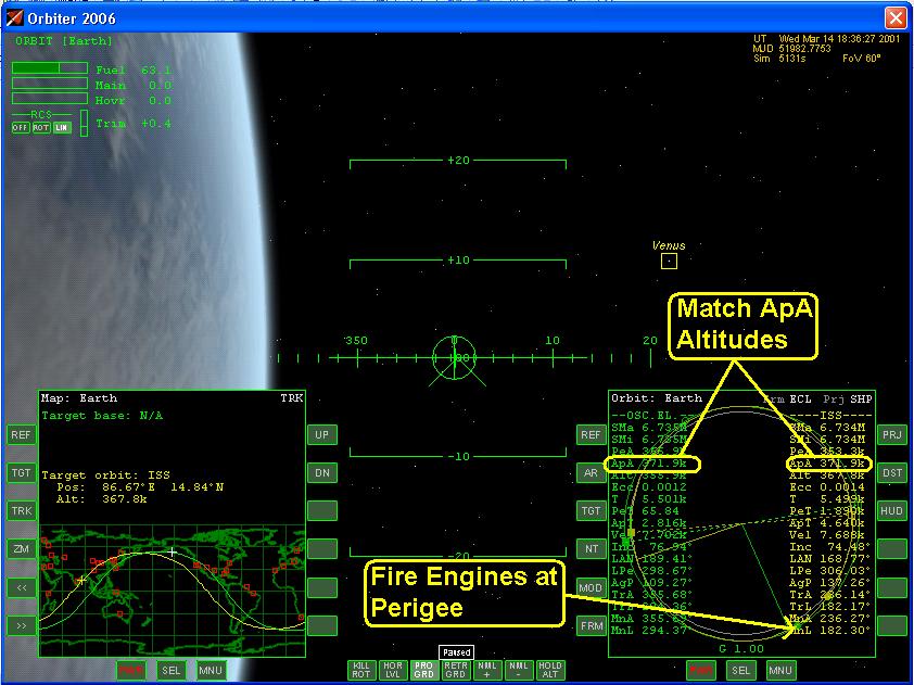
Section 2: Instrument Set Up The Orbital Mode of the Multi-function Display (MFD), Figure 2a, shows all of the current Orbital Element values, and a graphical depiction of the orbit. The apogee is mark with an open green circle, and the perigee is marked with a closed or filled green circle, Figure 2b. These points are where we will change the apogee or perigee altitudes. Figure 2c displays the numerical values of the Orbital Elements. You can toggle between the two using the MOD button. The green radius vector displays the ships current location in the orbit. Monitor the Orbital Elements as you adjust the perigee or apogee of the orbit.
Complete the check list items for the instrument setup: Section 3: Procedures
Complete the check list items for the procedure: Section 4: Completion of Maneuver The maneuver is complete when you have successfully adjusted the altitude of your orbit, and have properly circularize the orbit. The key points are to perform the maneuver at the apogee or perigee to the correct altitude, then appropriately adjusting the orbit until the eccentricity is nearly zero. Section 5: Summary Check List - Launching Into Orbit Listed below is a summary of the check list used in this lesson. A check list provides using abbreviated steps to help remind you of the action items that you need to take. They are listed here as a quick reference guide and are sited through out this lesson.
Citation Pictures: 1-Orbiter Space Flight Simulator, 2006 Edition User Manual, Martin Schweiger, pg 47 2-Orbiter Space Flight Simulator, 2006 Edition User Manual, Martin Schweiger, pg 53-54 3-Orbiter Space Flight Simulator, 2006 Edition User Manual, Martin Schweiger, pg 53-54 4-Orbiter Space Flight Simulator, 2006 Edition User Manual, Martin Schweiger, pg 53-54
|
|
|
Send mail to
customerservice@fly-zero-g.com with
questions or comments about this web site.
|