•
|
• |
|
|
Lesson Objectives In this tutorial you will learn the basic steps for Rotating and Aligning the Orbital Plane (OP). The following subjects will be presented.
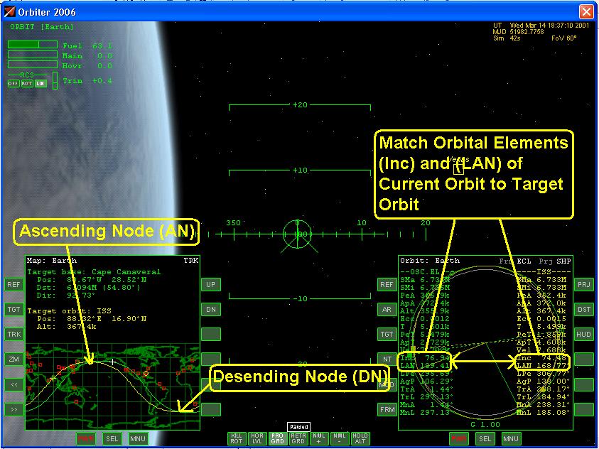
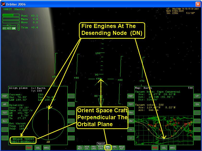
Section 1: Concept When trying to rendezvous with another object in orbit, the required orbit changes can often be simplified by splitting them into two separate phases: a plane change that rotates the plane of the current orbit and then aligning it with the orbital plane of the target orbit. The second phase in rendezvous with another space craft or space station are synchronization operations that only require the application of thrust in the plane of the orbit. To rotate the plane of the orbit requires that the thrust be applied at the precise time perpendicular to your orbit and at the intersection of where the two orbital planes meet, Figure 1a and 1b.
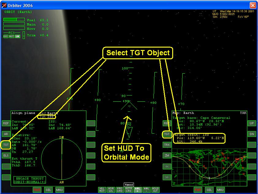
Once you are in the same plane as your target, most of the following navigational problems become essentially two-dimensional, which makes orbital maneuvers more robust and a lot easier to compute. In terms of the orbital elements, aligning the plane of the orbit with a target plane means to match the three Orbital Elements which define the orientation of the orbit in space: inclination (i) , eccentricity (Ecc), and longitude of the ascending node (W or LAN) (See Figure 1a and 1b). The rotation of the orbital plane requires the application of thrust perpendicular to the orbital plane, or out of plane thrust. To match the plane with a target plane, thrust should be applied normal to the current plane, at one of the nodes (the points where the orbit crosses the intersection of the current and target planes). This will rotate the orbital plane around an axis defined by your current radius vector. The amount of normal Delta v required to rotate plane is determined by angle between two planes and is proportional to the orbital velocity v. It is therefore more fuel-efficient to perform the plane change where orbital v is small, close to aphelion. For a given line of nodes, it is more efficient to perform the plane change at the node closer to aphelion. Sometimes it may even be useful to make the orbit more eccentric prior to the plane change maneuver, so that the radius distance of one of the nodes is increased. If the angle between the initial and target orbital plane is large it may be necessary to adjust the orientation of the spacecraft during the maneuver to keep it normal to the orbital plane. It may not be possible to align the plane in a single node crossing. It may take several orbits to change the orbital plane. If the angle towards the target plane cannot be reduced further by accelerating normal to the current orbit, cut the engines and wait for the next node crossing. Section 2: Instrument Setup The Align orbital plane MFD mode is designed to aid in plane alignment, Figure 2a and 2b. Select the target object Figure 2c. in this case the International Space Station. The HUD should be in Orbit mode. On the Map Mode of the MFD Select the TGT to be the ISS this will aid in determining when you are at one of the nodes.
Complete the checklist items for the instrument for set up: Section 3: Procedures for the Maneuver
Complete the procedure checklist items: Section 4: Completion of the Maneuver At the completion of the maneuver ensure that the orbital elements of the target object and your current orbit match Figure 4a. It may be necessary to repeat this orbital alignment procedure several times to match up both orbits. A good value for the relative inclination (Rinc) is about 0.03 degrees. You can fine tune this value use the RCS thrusters Figure 4b. Once you are satisfied with the alignment of the two planes rotate the space craft to a Prograde position and proceed with the next maneuver.
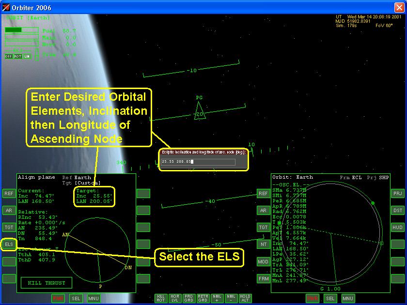
Section 5: Selecting Custom Orbital Elements A useful feature of the Align Orbital MFD mode is to be able to select custom Orbital Elements. If there is no target available such as space craft or space station then one can use this feature to select a precise orbital plane. This can be used to select an obit for deorbit to land at a space port or to select a different orientation about a planetary body. To use this feature select the ELS button and enter the desired inclination. Then complete the Orbital Alignment procedures.
Section 6: Summary Check List - Rotating and Aligning The Orbital Plane Listed below is a summary of the check list used in this lesson. A check list provides using abbreviated steps to help remind you of the action items that you need to take. They are listed here as a quick reference guide and are sited through out this lesson. Pictures: 1-Orbiter Space Flight Simulator, 2006 Edition User Manual, Martin Schweiger, pg 77 2-Orbiter Space Flight Simulator, 2006 Edition User Manual, Martin Schweiger, pg 64-65 3-Orbiter Space Flight Simulator, 2006 Edition User Manual, Martin Schweiger, pg 64-65 4-3-Orbiter Space Flight Simulator, 2006 Edition User Manual, Martin Schweiger, pg 47
|
|
|
Send mail to
customerservice@fly-zero-g.com with
questions or comments about this web site.
|